
流程图有助于理解逐步算法以设计工作流和流程的图形表示。在某些情况下,您可能需要创建流程图来解决问题。本文介绍如何在 Java 中以编程方式创建流程图。
安装 Java API 制作流程图
您可以使用 Aspose.Diagram for Java API 制作流程图。它支持以 VSD、VSDX 和其他 支持的格式 创建或编辑 Visio 文件。您可以通过从 New Releases 部分下载 JAR 文件或使用以下 Maven 规范轻松安装 API:
存储库:
 <repositories>
    <repository>
        <id>AsposeJavaAPI</id>
        <name>Aspose Java API</name>
        <url>http://repository.aspose.com/repo/</url>
    </repository>
</repositories>
依赖:
 <dependencies>
    <dependency>
        <groupId>com.aspose</groupId>
        <artifactId>aspose-diagram</artifactId>
        <version>22.1</version>
        <classifier>jdk16</classifier>
    </dependency>
</dependencies>
在 Java 中以编程方式制作流程图
您可以制作流程图来解释序列的步骤。您需要按照以下步骤制作流程图:
- 首先,创建用于创建图表的模式。
- 其次,加载一个 VSS 文件作为添加形状的主文件。使用 图表 类。
- 从架构中添加形状和连接器。
- 设置流程图的布局。
- 最后,使用 Save 方法以 VSDX 格式编写带有流程图的输出文件。
下面的代码示例详细说明了如何在 Java 中以编程方式制作流程图:
// 创建新图表
int pageNumber = 0;
String rectangleMaster = "Process", decisionMaster = "Decision", connectorMaster = "Dynamic connector";

Diagram diagram = new Diagram("XANFLOWCHARTNEW.vss");

double width = 1, height = 1, pinX = 4, pinY = 10;
long process1 = diagram.addShape(pinX, pinY, width, height, rectangleMaster, 0);
Shape processShape1 = diagram.getPages().getPage(pageNumber).getShapes().getShape(process1);

processShape1.getText().getValue().add(new Txt("PROCESS"));
processShape1.setName("PROCESS");
processShape1.getXForm().getLocPinX().getUfe().setF("Width*0.5");
processShape1.getXForm().getLocPinY().getUfe().setF("Height*0.5");

pinY = pinY - 2;

long decision1 = diagram.addShape(pinX, pinY, width, height, decisionMaster, 0);
Shape decisionShape1 = diagram.getPages().getPage(pageNumber).getShapes().getShape(decision1);

decisionShape1.getText().getValue().add(new Txt("DECISION"));
decisionShape1.setName("DECISION");
decisionShape1.getXForm().getLocPinX().getUfe().setF("Width*0.5");
decisionShape1.getXForm().getLocPinY().getUfe().setF("Height*0.5");

pinY = pinY - 2;
long process2 = diagram.addShape(pinX, pinY, width, height, rectangleMaster, 0);
Shape processShape2 = diagram.getPages().getPage(pageNumber).getShapes().getShape(process2);

processShape2.getText().getValue().add(new Txt("PROCESS"));
processShape2.setName("PROCESS");
processShape2.getXForm().getLocPinX().getUfe().setF("Width*0.5");
processShape2.getXForm().getLocPinY().getUfe().setF("Height*0.5");

pinY = pinY - 2;
long process3 = diagram.addShape(pinX, pinY, width, height, rectangleMaster, 0);
Shape processShape3 = diagram.getPages().getPage(pageNumber).getShapes().getShape(process3);

processShape3.getText().getValue().add(new Txt("PROCESS"));
processShape3.setName("PROCESS");
processShape3.getXForm().getLocPinX().getUfe().setF("Width*0.5");
processShape3.getXForm().getLocPinY().getUfe().setF("Height*0.5");

pinY = pinY - 2;
long process4 = diagram.addShape(pinX, pinY, width, height, rectangleMaster, 0);
Shape processShape4 = diagram.getPages().getPage(pageNumber).getShapes().getShape(process4);

processShape4.getText().getValue().add(new Txt("PROCESS"));
processShape4.setName("PROCESS");
processShape4.getXForm().getLocPinX().getUfe().setF("Width*0.5");
processShape4.getXForm().getLocPinY().getUfe().setF("Height*0.5");

long connecterId = diagram.addShape(new Shape(), connectorMaster, 0);
diagram.getPages().getPage(pageNumber).connectShapesViaConnector(process1, ConnectionPointPlace.BOTTOM,
        decision1, ConnectionPointPlace.TOP, connecterId);

long connecterId1 = diagram.addShape(new Shape(), connectorMaster, 0);
diagram.getPages().getPage(pageNumber).connectShapesViaConnector(decision1, ConnectionPointPlace.BOTTOM,
        process2, ConnectionPointPlace.TOP, connecterId1);

long connecterId2 = diagram.addShape(new Shape(), connectorMaster, 0);
diagram.getPages().getPage(pageNumber).connectShapesViaConnector(process2, ConnectionPointPlace.BOTTOM,
        process3, ConnectionPointPlace.TOP, connecterId2);

long connecterId3 = diagram.addShape(new Shape(), connectorMaster, 0);
diagram.getPages().getPage(pageNumber).connectShapesViaConnector(process3, ConnectionPointPlace.BOTTOM,
        process4, ConnectionPointPlace.TOP, connecterId3);

long connecterId4 = diagram.addShape(new Shape(), connectorMaster, 0);
diagram.getPages().getPage(pageNumber).connectShapesViaConnector(decision1, ConnectionPointPlace.RIGHT,
        process4, ConnectionPointPlace.TOP, connecterId4);

// 设置自动布局选项
LayoutOptions layoutOptions = new LayoutOptions();

// 方法
layoutOptions.setLayoutStyle(LayoutStyle.FLOW_CHART);
layoutOptions.setDirection(LayoutDirection.BOTTOM_TO_TOP);
diagram.layout(layoutOptions);

DiagramSaveOptions options = new DiagramSaveOptions(SaveFileFormat.VSDX);
diagram.save("sample.vsdx", options);
示例输出流程图预览
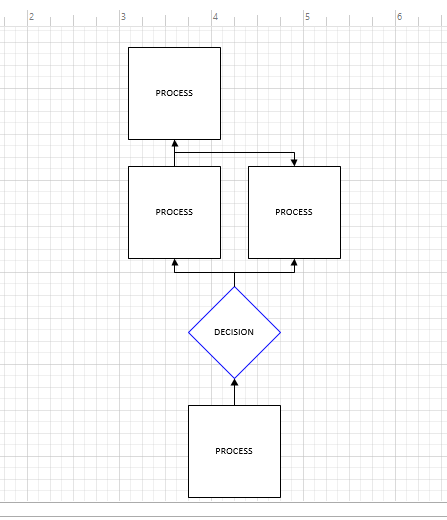
此外,您可能希望 下载 输入和输出文件来检查此功能。
获取免费 API 许可证
您可以通过申请 免费临时许可证 来不受任何限制地评估 API 的所有功能。
结论
总之,您已经学习了如何使用 Java 以编程方式创建或制作流程图。您可以根据需要自定义和更改流程图的方向或形状。因此,您可以使用 Java 应用程序中的 API 调用轻松嵌入此功能。此外,您可以访问 API 文档 以检查 API 的其他几个功能。您可以通过 论坛 联系来提出您的任何问题。